Analog Electronics Final Project – Jonathan Philip
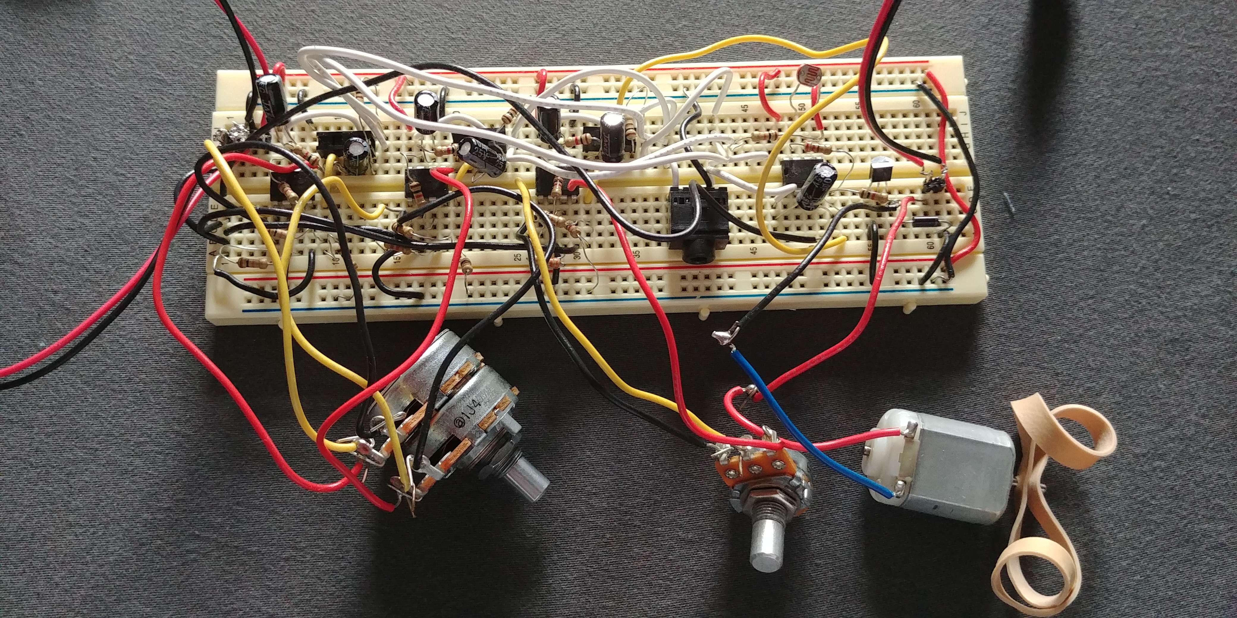
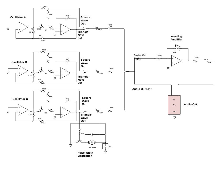
For my final project I built a synth containing 3 oscillators that output 3 varying frequencies of audio with the 3rd oscillator controlling the speed of a spinning motor. Each of these oscillators have a switch that changes the waveform of the audio from a triangle wave to a square wave. I have a dual 100K audio potentiometer (or knob) controlling the frequencies of Oscillators A and B and a single knob controlling the frequency of Oscillator C. The total output signal of the three oscillators is divided into two channels. The left channel goes straight into the audio jack at its full volume. The Right channel goes through an inverting amplifier circuit that is controlled by a photocell. As I put my finger over the photocell, the volume or amplitude of the signal in the right channel goes higher, as I remove it, it goes lower.
Oscillators
The first part of my circuit are the 3 Oscillators; A, B and C. The oscillator is a circuit that outputs an audio signal at a frequency based on one of the resistors used in the circuit. Each of the oscillators have both a square wave and triangle wave output and so a user has the option of choosing what type of sound they want to hear. Each of the oscillator circuits are pretty much the same except for one resistor that affects the frequency of the output.
The formula to calculate frequency is
f = (1/(4Rt*C))*(R2/R1)
where:
f- Frequency (Hz)
Rt- Resistance at Rt (The resistance between the output of the first Op Amp and – input of the second Op Amp)
R2- Resistance at R2 ( The resistance between the output and + input of the first Op Amp)
R1- Resistance at R1 (The resistance between the output of the second Op Amp and the + input of the first Op Amp)
C – is the Capacitor connected to the – input and output of the second Op Amp
The resistance that changes in each of the oscillator circuits is R2
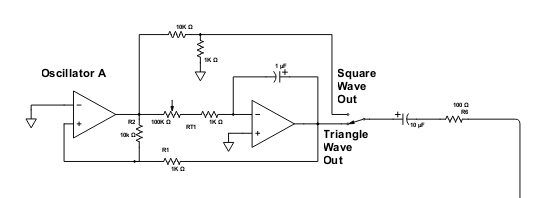
In oscillator A we can see that R2 is 10k Ohms, R1 is 1K ohms and RT consists of a 100K ohm potentiometer and a 1K ohm regular resistor. There is also a 1 micro Farad capacitor
A potentiometer is a resistor that can change its resistance based on how far clockwise or anti-clockwise you turn the knob. Because this one is 100K ohms, the resistance goes from (about) 10 ohms all the way up to 100K ohms giving a wide range of frequencies (from low to high)
Therefore, if we use the formula given for Oscillator A,
the highest output frequency would be:
f = (1/(4*(10+1000)*0.000001))*(10,000/1000)= 2,475Hz
and the lowest:
1/(4*(100,000+1000)*0.000001))*(10,000/1000)= 25Hz
At the end of the circuit is a switch that lets you switch from the top part of that schematic which is where the square wave is generated from and the bottom part which is the triangle wave. You may use the switch to decide which signal you want to hear.
After the switch is a DC blocking circuit consisting of a resistor and a capacitor. Putting the resistor and capacitor one after the other is a small circuit that is used to protect the transducer (headphones/speaker) that I connect to my audio jack to listen to my synth by preventing the flow of Direct current.
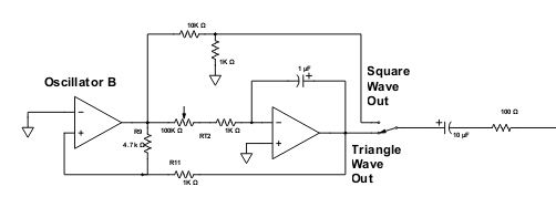
Oscillator B is the same as A except that R2 is 4.7K Ohms.
Therefore, if we use the formula given for Oscillator A,
the highest output frequency would be:
f = (1/(4*(10+1000)*0.000001))*(4,700/1000)= 1,163Hz
and the lowest:
1/(4*(100,000+1000)*0.000001))*(4,700/1000)= 12Hz
Oscillator B therefore gives an output audio that has a lower range of frequencies than Oscillator A
The interesting thing about Oscillators A & B is that they are connected to the same dual potentiometer at RT. A Dual potentiomenter is one that has one knob that controls two potentiometers at the same time, therefore, the total resistance at RT in A & B are raised or lowered in parallel. This gives and interestingly pleasing dissonance as we spin the knob in either direction.
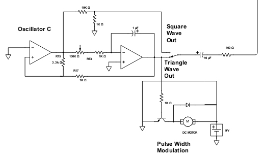
Oscillator C is where things get interesting. Although most of the circuit is the same as A&B, just like B, R2 has a different resistance from the other 2. R2 is 3.3K ohms which would give it a lower range of frequencies than the other 2.
Therefore, if we use the formula given for Oscillator C,
the highest output frequency would be:
f = (1/(4*(10+1000)*0.000001))*(3,300/1000)= 816Hz
and the lowest:
1/(4*(100,000+1000)*0.000001))*(3,300/1000)= 8Hz
Pulse Width Modulation
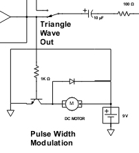
Connected to the Triangle wave output of Oscillator C is a Pulse Width Modulation circuit. Basically, using a resistor, transistor and diode we are able to use the waveform of the triangle wave output to control the speed of a DC motor. The way PWM works is just as it sounds. Sound is more or less a bunch of waves that oscillate back and forth in over a certain period of time. The pitch or key of a sound is determined by its frequency, or how frequently that wave goes back and forth within the frame of a second. Therefore, higher frequencies have more up and down movement than lower frequencies.

If we took a snapshot of one second of a sound signal, we could see how many of the peaks of the wave there are, and also how wide the wave form is. Normally, the wider the waveform, the less peaks and so there would be a lower frequency. The PWM circuit therefore uses the width of the waveform to control the speed of the motor, wider = lower frequency = slower spin and narrower = higher frequency = faster spin.
I connected the motor to Oscillator C because it has the lowest range of frequencies and because of the relationship between the range of frequencies and the range of speeds of the motor, lower frequencies would allow us to see a more obvious switch in speeds of the motor.
The motor is also connected to its own power source so as to not interfere with the audio signal that we can hear.
Audio Out

I divided my audio output signal into two so that I could hear it in stereo. The left channel goes straight to the audio jack where you can plug your headphones or speaker in to listen.
The right channel however goes into an inverting amplifier circuit that uses a photocell to control the volume. A photocell is a type of resistor that uses light to determine its resistance. The more light there is, the more resistant, the less light, less resistance. This circuit allows me to control the volume of my right audio channel by adjusting how much light the photocell is exposed to. Therefore, if I place my finger over the photocell it gets louder and when I remove it it gets louder.
The formula for calculating how much of a gain my signal has is as follows:
Vout = -Vin*(Rf/Rin)
Vout – Voltage or loudness of the signal coming out of the circuit
Vin – Volatage or loudness of the signal going into the circuit
Rf – Resistance of the Photocell
Rin – Resistance at the beginning of the circuit
If my battery is 9V
And my photocell (measured) is about 200kOhms at its greatest resistance and about 10 ohms at its lowest
Completely exposed to light my Gain or voltage out is
-9*(200,000/10,000) = -180 or 180 times as soft as it originally was
In complete darkness my Gain or voltage out is
-9*(20/10,000) = -0.018 or almost close enough to its original volume
At the end of my inverting amplifier circuit is another DC blocking circuit that goes to the right side of the jack so that the output does not damage the audio device that I have connected to the jack.
This circuit allows me to more or less switch between mono and stereo sound just by placing and removing my finger from the photocell.

Leave A Comment?